Equipment
Hydraulic Systems
HYDRAULIC PRINCIPLE - PASCAL LAW
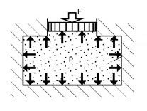
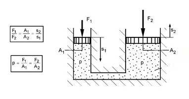
The principle of the hydrostatic displacement machine is based on Pascal's Law, which states: "The pressure applied anywhere to a body of liquid causes a force to be transmitted equally in all directions. This force acts at right angles to any surface. internal or in contact with the fluid contained. ” The static pressure in a fluid thus allows the force to be transferred. Figure 1.1 illustrates Pascal's hydrostatic principle. Figure 1.2 shows the principle of a hydraulic press.


In a hydraulic system, energy input is called "driving force". Electric engines and internal combustion engines are examples of driving forces. Hydraulic pumps and boosters do not create energy; they simply convert them to a form that can be used by a hydraulic system.
The transfer of hydraulic power is characterized by the simplicity of its elements, long life, high performance and economy. The variety of hydraulic applications is largely determined by the behavior of the hydraulic fluid.
The most important elements of a hydraulic system are:
- Pumps and motors (pumps, for example gears, vane and piston)
- Hydraulic cylinders (for example, single and double acting)
- Valves (for example, pressure limiters and control valves)
- Circuit components (for example, fluid reservoirs, filter systems, pressure tanks, piping, etc.)
- Seals, joints and elastomers
HYDRAULIC PUMPS
The pumps are used in hydraulic circuits to convert mechanical energy into hydraulic energy. The pump is often described in terms of its pressure limitations. They are called positive displacement pumps and differ from centrifugal types, such as water pumps and fans, because the flow and pressure energies are generated in an enclosed space.
| Type | Piston Pump | Vane Pump | Gear Pump |
|---|---|---|---|
| Estructure | ![Performance Degradation Analysis of Aviation Hydraulic Piston Pump Based on Mixed Wear Theory - Scientific Figure on ResearchGate. Available from: https://www.researchgate.net/figure/The-structure-of-axial-piston-pump_fig1_317816283 [accessed 31 Aug, 2020] Piston pump](../_imagens/estrutura-de-bomba-de-pistao.png) |
 |
 |
| Operation | Expansion and compression of a volume in a cylinder block with the piston stroke. | Expansion and compression of volumes between the vanes and the cam ring. | Movement of volumes between the spaces of the teeth and the housing. |
| Eficiency |
|
|
|
| Contamination Resistance | Highly susceptible to foreign substances in the oil | Susceptible to foreign substances in the oil, but less than piston pumps | Susceptible to foreign substances in the oil, but hardly susceptible when the pumps are of the low pressure type |
| Suction Capacity | Low | Middle | High |
| Variable offset type | Easy to convert by changing the angle of the oscillating plate or bent axis. | It can be converted by changing the cam ring eccentricity to the unbalanced type. | Difficult |
| Size and Price | Generally large, heavy and expensive | The smallest and relatively cheap | Small, light and cheap |
GEAR PUMPS
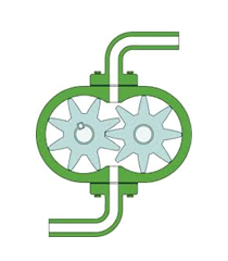
These pumps operate with two gears engaged with each other and rotating to feed a hydraulic fluid from the suction area to the discharge area. They all have fixed (constant) displacement capabilities. They are categorized into external and internal gear pumps; the internal type generally has a lower discharge pulse and a lower noise level than the other. Gear pumps are relatively resistant to contamination of the working fluid.
High-pressure gear pumps often adopt wrap-around gears, which allow for highly accurate processing, bringing high system operating efficiency. In contact with each other at two points, the gears rotate to hold the oil in the coupling parts, resulting in vibration and noise, which are reduced by a groove in the side plate allowing the oil to escape. Some low pressure gear pumps use trochoid gears.
The displacement of the external gear pumps is determined by a chamber between the neighboring gear teeth and the inner surface of the housing; the displacement of the internal gear pump is determined by a chamber between the external and internal gears and an instrument panel. The crescent shaped panel (filling piece) separates the suction and discharge areas. For both types, the sides of the gear teeth are sealed with side plates. High pressure external gear pumps have a movable side plate through which the high pressure flow is directed to the rear side to press against the gear and maintain adequate clearance.
VANE PUMPS
These pumps absorb and discharge fluid according to the change in space between the vanes and the cam ring that rotates through the rotor. These pumps offer the following advantages: (1) minimized discharge pressure pulsation; (2) compactness and light weight for high performance; (3) less degradation of efficiency due to the wear of the blades and; (4) reliability and ease of maintenance.
Vane pumps are categorized into fixed and variable displacement types. Each type is further subdivided into single and multiple pumps. With vane pumps, it is easy to build double and triple pumps by assembling the pump elements (components such as rotors, vane and cam rings) together with the pump shaft.
Single Vane Pumps
They have a simple structure: the clearances between the rotor and the vane side are maintained with a fixed plate. The inner space of the cam ring is structured with an oval circle and a complete round circle. The curved, connected space between the circles is where the vanes make the lifting movement. The pumps have two pairs of suction and discharge areas and balance the internal radial force with the discharge pressure; therefore, these pumps are called the balanced pressure type.
Multiple Vane Pumps
These pumps are categorized into double and triple types. The dual pump has two sets of cartridge kits on one axis and each kit works independently. This type generally contains a combination of high volume low pressure elements and low volume high pressure pump elements. The triple pump has three sets of cartridge kits and forms a circuit to sum up the outlet pressures for applications that require greater displacement.
Variable Displacement Vane Pumps
The vane pumps can be transformed into the unbalanced type by making the center of the round cam ring eccentric to the rotating shaft; this type provides a couple of suction and discharge processes. The pumps can also be converted to the variable displacement type, making the cam ring at maximum eccentricity concentric with the shaft (the outflow continuously reduces to zero). The type of variable displacement is not pressure balanced and has a greater force in the radial direction than the type of fixed displacement.
PISTON PUMPS
These pumps guarantee high performance in high pressure operation compared to other types, and are easy to convert to the variable displacement type. Thus, they can operate with various types of control. Piston pumps offer advantages, including: (1) high efficiency; (2) ease of operation at high pressure; (3) ease of conversion to the type of variable displacement, and; (4) various types of control applicable.
Piston pumps are categorized into axial, radial and reciprocal piston types.
Axial Piston Pumps
These pumps have pistons installed in parallel or axially with the pump shaft. The pumps are subcategorized in type of oscillating plate and type of curved shaft according to the piston stroke mechanism.
For both types, the displacement of the pump depends on the stroke of the pistons in the cylinder block. The maximum angle displacement of the oscillating plate or bent axis represents the size of the pump. The pumps operate with the cylinder block rotating on the shaft. The cylinder block comes into contact and rotates on the valve plate (or door plate), which is attached opposite the piston, to provide alternate suction and discharge. Some of the oscillating plate type axial piston pumps have a fixed cylinder block and a rotating oscillating plate, which rotates so that the piston moves. This type uses a check valve on each cylinder to alternate suction and discharge.
Radial Piston Pumps
These pumps have pistons installed in a radial pattern to the axis of rotation of the pump. The pumps are more suitable for high pressure operation than the axial type. The piston stroke is achieved with an eccentricity from the piston sliding ring to the rotating shaft of the pump. These pumps exchange suction and discharge for the piston stroke in the ring. With an eccentricity change mechanism for the ring added, the pumps allow their displacement to be adjusted.
Reciprocal Pumps
These pumps have pistons installed at right angles against the axis of rotation of the pump in a plane that includes the axis. The pistons alternate with mobile cranks or eccentric cams. These pumps are used for high pressure applications, such as construction vehicles, cargo loading machines and presses. In addition, they can handle water or water-containing fluids as the working fluid due to the construction being a wider applicable area for lubrication.
VALVES
Valves are mechanisms that control the starting, stopping, steering or flow of a hydraulic medium from a pump or pressure vessel. Current trends in industries include miniaturization of traditional designs and stackable valves to save space. The valves are being manufactured from more modern materials; Plastics are used to reduce weight, improve lubricity and improve corrosion resistance. Ceramics are being used to increase the life of the valve and improve resistance to contamination.
The valves used in the hydraulic industry are instruments manufactured with precision. Since precision in construction and tight tolerances reduce fluid leakage to a negligible amount, hydraulic valves, in general, do not require sealing material. Tight tolerance in construction is a basic reason to use only the best hydraulic fluids that do not oxidize in service and prevent rust. Oxidation and rust can cause the valves to clamp, clog small openings or grind small surfaces.
Flow valves already have preset switching points. Proportional valves and servo valves are electro-hydraulic, that is, their movement is proportional to the electrical input signal. The differences between these valves are their mechanical design, their static and dynamic properties, and their price. The hydraulic fluid in a valve must dissipate heat, reduce wear, minimize friction, and prevent corrosion. Equally important, it must not form deposits in the narrow gaps found in valves. Long fluid change intervals and high thermal loads (for example, caused by magnetic solenoids) should not lead to deposits or resin on the flow valves.
- Relief valve: the function of any relief valve is to protect the hydraulic system against excess pressure if the pressure exceeds a predetermined maximum value. A relief valve is an automatic relief device, which is activated by the static pressure upstream of the valve. The relief valves are designed to return hydraulic fluid directly to the reservoir. Normally, a relief valve remains closed until the system pressure approaches a predetermined value. As the system pressure increases to the opening pressure, the valve begins to open, the flow volume, through a properly sized relief valve, will increase until the entire flow of the pump passes through the valve. When the system pressure drops, the valve closes smoothly and slowly.
- Pressure Reduction Valve: a pressure reduction valve is used to limit the normal pressure level of the primary or primary system to the pressure required for a secondary or derivative hydraulic circuit.
- Pressure Sequence Valve: Pressure sequence valves establish flow priorities within a hydraulic circuit. They are used to determine the sequence of machine operations, sensing pressures and repositioning themselves to divert fluid flow.
- Discharge Valve: the discharge valves return the fluid to the reservoir when the circuit pressure increases to a predetermined maximum.
- Flow Control Valve: Flow control valves control the volume in hydraulic circuits. The flow is controlled either by throttling or diverting the flow. Strangling the flow implies reducing the size of an opening until the flow cannot pass through the hole; diverting the flow implies that part of the flow does not enter the circuit so that the driven device receives only a part of the flow necessary to perform its task.
- Directional Control Valve: Directional control valves are used to direct the flow of hydraulic fluid and drive cylinders, hydraulic motors and other drive units. Because it is fast-acting and easy to operate, the coil-type valve is widely used in hydraulic systems for steering control. These valves contain a moving coil that opens or closes passages to control the direction of fluid flow.
HYDRAULIC ACTUATORS
Hydraulic actuators convert working energy into mechanical energy. They are the points from which all visible activity occurs and are one of the main items to be considered when designing the machine. They are divided into two types: linear and rotary.
Hydraulic Cylinders
Hydraulic cylinders transform hydraulic work into linear mechanical energy.
A cylinder consists of a jacket (tube), a movable piston and a rod connected to the piston. The heads are attached to the cylinder by means of threads, fasteners, tie rods or welding. As the rod moves in or out, it is guided by bushes (removable bearing assembly with linings). The side for which the rod operates is called the front side or “cylinder head”. The opposite side without the rod is the rear side. The inlet and outlet holes are located on the front and rear sides.
Rotary Actuators
These mechanisms are compact, simple and efficient. They produce high torque and require little space and simple assembly.
Hydraulic motors
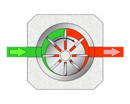
Hydraulic motors can be connected directly or through gears to the driven part. They can be of the piston, gear or vane type.
Radial and axial piston engines are constructed in much the same way as piston pumps. The pistons are extended by the high pressure fluid. When the hydraulic fluid pushes the pistons, they generate rotating force.
Gear motors are the most common type of hydraulic motors, being the most common gear-on-gear motor.
Mobile vane motors are constructed in a similar way to mobile vane pumps.
In general, actuators are applied in indexing machine tools, folding operations, lifting or rotating heavy objects, folding functions, positioning, machining devices, rudder actuators, etc.
- Hydraulic oscillators: convert hydraulic energy into rotary motion over a number of degrees. The hydraulic oscillator is a rotary actuator with limited turning range.
- Rack and pinion oscillator: this type of rotary actuator provides uniform torque in both directions and across the entire rotation field. Rack and pinion units of the standard type can be found in rotation of 90, 180, 360 degrees or more.
- Vane oscillator: these models are provided with maximum torque output value for a reduced size. Used for a wide variety of industrial applications, they are available in a single vane model and have a maximum rotation angle of 280 degrees.
HYDRAULIC ACCUMULATORS
Accumulators store the potential energy of a fluid for subsequent conversion to useful work. The potential energy can be in the form of gravitational work, spring elasticity or gas compressibility.
Accumulators are used to eliminate pump pulsations, absorb shock from pressure surges, compensate for leakage and maintain a safe pressure at a constant level over a long period, to maintain sufficient pressure to operate secondary or emergency circuits and operate as a transfer barrier between two separate fluid systems, such as: a hydraulic fluid and a corrosive fluid.
There are three general types of accumulators: loaded with weight, loaded with spring and hydropneumatic.
- Weight-loaded accumulators: a weight-loaded accumulator applies a force to the liquid by means of a heavy load. As the weights do not change, accumulators loaded by weight are characterized by pressure, which is constant throughout the piston stroke.
- Spring loaded accumulators: consists of cylinder housing, movable piston and spring. The spring applies force to the piston, which results in the pressure of the liquid. As the liquid is pumped into the spring-loaded accumulator, the pressure in the reservoir is determined by the compression rate of the spring. Spring loaded accumulators are more flexible than the weight loaded type. They are smaller and can be mounted in any position.
- Hydropneumatic accumulators: this type of accumulator applies the force of the liquid using a compressed gas, which acts as a spring, also working with variable pressure. They are divided into types: piston, diaphragm and bladder. The name of each type indicates how the liquid is separated from the gas.
- Piston type: the gas that occupies the volume above the piston is compressed as the liquid is forced into the housing. When the piston is full, the gas pressure equals the system pressure.
- Diaphragm type: usually has a spherical shape divided into two metal hemispheres, which are separated by means of a synthetic rubber diaphragm. The gas occupies one chamber and the liquid enters the other.
- Bladder type: consists of a synthetic rubber bladder inside a metal housing. The bladder is filled with compressed gas. A seat-type valve, located in the outlet port, closes the port when the accumulator is completely empty and prevents the bladder from being extruded into the system.
RESERVOIRS
Although the basic function of a reservoir is to provide an adequate amount of fluid for the entire hydraulic system, it is more than a simple fluid storage container. The reservoirs also supply extra fluid to the system in the event of a leak or cylinder extension. In addition, most reservoirs allow the fluid that returns turbulent from the hydraulic system to rest and deflate.
Reservoirs must be completely closed and independent. They must be divided into at least two compartments by vertical screens. The screens separate the return fluid from the fluid that enters the pump suction. The separation allows air and other contaminants to separate from the fluid. Contact with the bulkhead also allows the fluid to cool. The return line and the suction line must enter the reservoir through opposite sides of a bulkhead.